written by: naveenagrawal • edited by: Lamar Stonecypher • updated: 11/22/2009
Hydraulic
Turbines transfer the energy from a flowing fluid to a rotating shaft. Turbine
itself means a thing which rotates or spins. To know more about what are
Hydraulic Turbines, what is the working principle of Hydraulic Turbines and how
are they classified, read on through this article series.
·
Leonardo da
Vinci once said “The power of water has changed more in this world than
emperors or kings”. It was very rightly stated by him as in present time
Hydropower, the power generated from water, has a major contribution to the
world’s total power production. This all was made possible by the development
of Hydraulic Turbines which can transfer the energy from flowing water to the
shafts of dynamos producing electrical power.
·
Hydraulic Turbines
Hydraulic
Turbines have a row of blades fitted to the rotating shaft or a rotating plate.
Flowing liquid, mostly water, when pass through the Hydraulic Turbine it
strikes the blades of the turbine and makes the shaft rotate. While flowing
through the Hydraulic Turbine the velocity and pressure of the liquid reduce,
these result in the development of torque and rotation of the turbine shaft.
There are different forms of Hydraulic Turbines in use depending on the
operational requirements. For every specific use a particular type of Hydraulic
Turbine provides the optimum output.
·
Classification of Hydraulic Turbines: Based on flow path
Water can
pass through the Hydraulic Turbines in different flow paths. Based on the flow
path of the liquid Hydraulic Turbines can be categorized into three types.
1. Axial Flow Hydraulic Turbines: This category of Hydraulic Turbines
has the flow path of the liquid mainly parallel to the axis of rotation. Kaplan
Turbines has liquid flow mainly in axial direction.
2. Radial Flow Hydraulic Turbines: Such Hydraulic Turbines has the
liquid flowing mainly in a plane perpendicular to the axis of rotation.
3. Mixed Flow Hydraulic Turbines: For most of the Hydraulic Turbines
used there is a significant component of both axial and radial flows. Such
types of Hydraulic Turbines are called as Mixed Flow Turbines. Francis Turbine
is an example of mixed flow type, in Francis Turbine water enters in radial
direction and exits in axial direction.
None of the
Hydraulic Turbines are purely axial flow or purely radial flow. There is always
a component of radial flow in axial flow turbines and of axial flow in radial
flow turbines.
·
Classification of Hydraulic Turbines: Based on pressure change
One more
important criterion for classification of Hydraulic Turbines is whether the
pressure of liquid changes or not while it flows through the rotor of the
Hydraulic Turbines. Based on the pressure change Hydraulic Turbines can be
classified as of two types.
1. Impulse Turbine: The pressure of liquid does not
change while flowing through the rotor of the machine. In Impulse Turbines
pressure change occur only in the nozzles of the machine. One such example of
impulse turbine is Pelton Wheel.
2. Reaction Turbine: The pressure of liquid changes
while it flows through the rotor of the machine. The change in fluid velocity
and reduction in its pressure causes a reaction on the turbine blades; this is
where from the name Reaction Turbine may have been derived. Francis and Kaplan
Turbines fall in the category of Reaction Turbines.
Hydraulic Turbines
Hydraulic
Turbines transfer the energy from a flowing fluid to a rotating shaft. Turbine
itself means a thing which rotates or spins. To know more about what are
Hydraulic Turbines, what is the working principle of Hydraulic Turbines and how
are they classified, read on through this article series.
Basic Design
Pekerjaan hydromekanik terdiri dari perencanaan Turbin sebagai peralatan utama dan berbagai peralatan fasilitas operasi maupun peralatan pendukung dengan uraian singkat sebagai berikut.
Turbin sebagai peralatan utama terdiri dari runner, stay ring, wicket gate, spiral casing, draft tube, shaft, dan lain-lain. Untuk keperluan operasi turbin dilengkapi dengan berbagai peralatan operasi terdiri dari governor dan servomotor, inlet gate dan actuator, sistem pelumas, sistem pendingin bearing, sistem drainase ruang turbin dan sistem drainase draft tube. Dan untuk keperluan pemeliharaan turbin dilengkapi dengan peralatan pendukung yang terdiri dari Pintu intake, Pintu draft tube, Overhead travelling crane sistem pemadam kebakaran.
-Pengumpulan data: Perencanaan dasar berdasar Technical Standards akan diawali dengan pekerjaan pengumpulan data antara lain, Debit per DKD (10 harian) selama >10 dan Rencana elevasi muka air di regulating pond dan di tail race serta debit yang tersedia untuk keperluan perencanaan sebagai berikut : Flow-duration curve, Optimalisasi enersi, Menentukan kapasitas terpasang, Menentukan head rata-rata, Menghitung hydrolik losses, Menghitung net head, Menentukan jenis & jumlah turbin Menghitung output unit turbin, Hitung potensi enersi yang dapat dihasilkan, Optimal Enersi
Desain Dasar : Mengitung kecepatan spesifik, Menghitung kecepatan rotasi, Menghitung diameter runner Menghitung dimensi spiral casing, Menghitung dimensi draft tube, Menentukan elevasi runner Menentukan elevasi lantai generator,
Estimasi dimensi : diperlukan untuk menentukan ukuran bangunan PLTA maupun kedalaman bangunan Peralatan Operasi : Adalah peralatan yang dipergunakan untuk operasi turbin
Peralatan Pendukung : Adalah berbagai peralatan yang digunakan untuk pemeliharaan
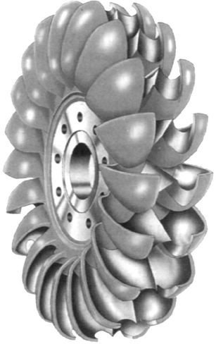
The Pelton
Turbine has a circular disk mounted on the rotating shaft or rotor. This
circular disk has cup shaped blades, called as buckets, placed at equal spacing
around its circumference. Nozzles are arranged around the wheel such that the
water jet emerging from a nozzle is tangential to the circumference of the
wheel of Pelton Turbine. According to the available water head (pressure of
water) and the operating requirements the shape and number of nozzles placed
around the Pelton Wheel can vary.

In a Pelton
Turbine or Pelton Wheel water jets impact on the blades of the turbine making
the wheel rotate, producing torque and power. Learn more about design, analysis,
working principle and applications of Pelton Wheel Turbine.
·
Working Principle of Pelton Turbine
The high
speed water jets emerging form the nozzles strike the buckets at splitters,
placed at the middle of a bucket, from where jets are divided into two equal
streams. These stream flow along the inner curve of the bucket and leave it in
the direction opposite to that of incoming jet. The high speed water jets
running the Pelton Wheel Turbine are obtained by expanding the high pressure
water through nozzles to the atmospheric pressure. The high pressure water can
be obtained from any water body situated at some height or streams of water
flowing down the hills.
The change
in momentum (direction as well as speed) of water stream produces an impulse on
the blades of the wheel of Pelton Turbine. This impulse generates the torque
and rotation in the shaft of Pelton Turbine. To obtain the optimum output from
the Pelton Turbine the impulse received by the blades should be maximum. For
that, change in momentum of the water stream should be maximum possible. That
is obtained when the water stream is deflected in the direction opposite to
which it strikes the buckets and with the same speed relative to the buckets.
·
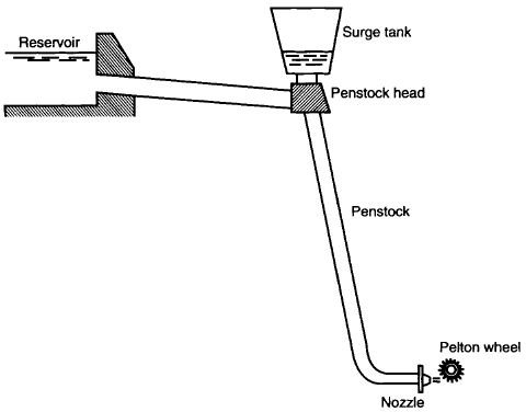
Pelton Turbine Hydroelectric Setup
A typical
setup of a system generating electricity by using Pelton Turbine will have a
water reservoir situated at a height from the Pelton Wheel. The water from the
reservoir flows through a pressure channel to the penstock head and then
through the penstock or the supply pipeline to the nozzles, from where the
water comes out as high speed jets striking the blades of the Pelton Turbine.
The penstock head is fitted with a surge tank which absorbs and dissipates
sudden fluctuations in pressure

For a
constant water flow rate from the nozzles the speed of turbine changes with changing
loads on it. For quality hydroelectricity generation the turbine should rotate
at a constant speed. To keep the speed constant despite the changing loads on
the turbine water flow rate through the nozzles is changed. To control the
gradual changes in load servo controlled spear valves are used in the jets to
change the flow rate. And for sudden reduction in load the jets are deflected
using deflector plates so that some of the water from the jets do not strike
the blades. This prevents over speeding of the turbine.
- Francis Turbine is the first hydraulic turbine with radial inflow. It was designed by American scientist James Francis. Francis Turbine is a reaction turbine. Reaction Turbines have some primary features which differentiate them from Impulse Turbines. The major part of pressure drop occurs in the turbine itself, unlike the impulse turbine where complete pressure drop takes place up to the entry point and the turbine passage is completely filled by the water flow during the operation.
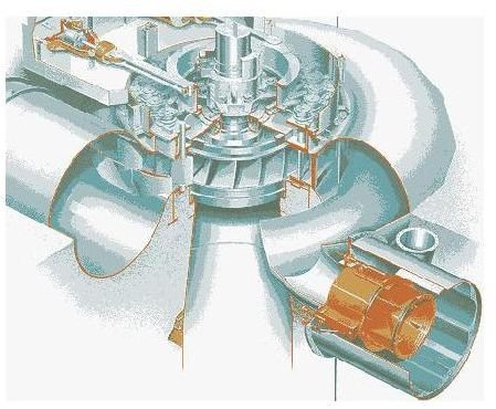
Design of Francis Turbine
Francis Turbine has a circular plate fixed to the rotating shaft perpendicular to its surface and passing through its center. This circular plate has curved channels on it; the plate with channels is collectively called as runner. The runner is encircled by a ring of stationary channels called as guide vanes. Guide vanes are housed in a spiral casing called as volute. The exit of the Francis turbine is at the center of the runner plate. There is a draft tube attached to the central exit of the runner. The design parameters such as, radius of the runner, curvature of channel, angle of vanes and the size of the turbine as whole depend on the available head and type of application altogether.
Working of Francis Turbine
Francis Turbines are generally installed with their axis vertical. Water with high head (pressure) enters the turbine through the spiral casing surrounding the guide vanes. The water looses a part of its pressure in the volute (spiral casing) to maintain its speed. Then water passes through guide vanes where it is directed to strike the blades on the runner at optimum angles. As the water flows through the runner its pressure and angular momentum reduces. This reduction imparts reaction on the runner and power is transferred to the turbine shaft.If the turbine is operating at the design conditions the water leaves the runner in axial direction. Water exits the turbine through the draft tube, which acts as a diffuser and reduces the exit velocity of the flow to recover maximum energy from the flowing water.Power Generation using Francis Turbine
For power generation using Francis Turbine the turbine is supplied with high pressure water which enters the turbine with radial inflow and leaves the turbine axially through the draft tube. The energy from water flow is transferred to the shaft of the turbine in form of torque and rotation. The turbine shaft is coupled with dynamos or alternators for power generation. For quality power generation speed of turbine should be maintained constant despite the changing loads. To maintain the runner speed constant even in reduced load condition the water flow rate is reduced by changing the guide vanes angle.

- Most of the turbines developed earlier were suitable for large heads of water. With increasing demand of power need was felt to harness power from sources of low head water, such as, rivers flowing at low heights. For such low head applications Viktor Kaplan designed a turbine similar to the propellers of ships. Its working is just reverse to that of propellers. The Kaplan Turbine is also called as Propeller Turbine.
Design of Kaplan Turbine
To generate substantial amount of power from small heads of water using Kaplan Turbine it is necessary to have large flow rates through the turbine. Kaplan Turbine is designed to accommodate the required large flow rates. Except the alignment of the blades the construction of the Kaplan Turbine is very much similar to that of the Francis Turbine. The overall path of flow of water through the Kaplan Turbine is from radial at the entrance to axial at the exit. Similar to the Francis Turbine,Kaplan Turbine also has a ring of fixed guide vanes at the inlet to the turbine.Unlike the Francis Turbine which has guide vanes at the periphery of the turbine rotor (called as runner in the case of Francis Turbine), there is a passage between the guide vanes and the rotor of the Kaplan Turbine. The shape of the passage is such that the flow which enters the passage in the radial direction is forced to flow in axial direction. The rotor of the Kaplan Turbine is similar to the propeller of a ship. The rotor blades are attached to the central shaft of the turbine. The blades are connected to the shaft with moveable joints such that the blades can be swiveled according to the flow rate and water head available.The blades of the Kaplan Turbine are not planer as any other axial flow turbine; instead they are designed with twist along the length so as to allow swirling flow at entry and axial flow at exit.Working of the Kaplan Turbine
The working head of water is low so large flow rates are allowed in the Kaplan Turbine. The water enters the turbine through the guide vanes which are aligned such as to give the flow a suitable degree of swirl determined according to the rotor of the turbine. The flow from guide vanes pass through the curved passage which forces the radial flow to axial direction with the initial swirl imparted by the inlet guide vanes which is now in the form of free vortex.The axial flow of water with a component of swirl applies force on the blades of the rotor and looses its momentum, both linear and angular, producing torque and rotation (their product is power) in the shaft. The scheme for production of hydroelectricity by Kaplan Turbine is same as that for Francis Turbine.

Causes of Cavitation
The liquid enters hydraulic turbines at high pressure; this pressure is a combination of static and dynamic components. Dynamic pressure of the liquid is by the virtue of flow velocity and the other component, static pressure, is the actual fluid pressure which the fluid applies and which is acted upon it. Static pressure governs the process of vapor bubble formation or boiling. Thus, Cavitation can occur near the fast moving blades of the turbine where local dynamic head increases due to action of blades which causes static pressure to fall. Cavitation also occurs at the exit of the turbine as the liquid has lost major part of its pressure heads and any increase in dynamic head will lead to fall in static pressure causing Cavitation.Detrimental Effects of Cavitation
The formation of vapor bubbles in cavitation is not a major problem in itself but the collapse of these bubbles generates pressure waves, which can be of very high frequencies, causing damage to the machinery. The bubbles collapsing near the machine surface are more damaging and cause erosion on the surfaces called as cavitation erosion. The collapses of smaller bubbles create higher frequency waves than larger bubbles. So, smaller bubbles are more detrimental to the hydraulic machines.Smaller bubbles may be more detrimental to the hydraulic machine body but they do not cause any significant reduction in the efficiency of the machine. With further decrease in static pressure more number of bubbles is formed and their size also increases. These bubbles coalesce with each other to form larger bubbles and eventually pockets of vapor. This disturbs the liquid flow and causes flow separation which reduces the machine performance sharply. Cavitation is an important factor to be considered while designing Hydraulic Turbines.
Avoiding Cavitation
To avoid cavitation while operating Hydraulic Turbines parameters should be set such that at any point of flow static pressure may not fall below the vapor pressure of the liquid. These parameters to control cavitation are pressure head, flow rate and exit pressure of the liquid. The control parameters for cavitation free operation of hydraulic turbines can be obtained by conducting tests on model of the turbine under consideration. The parameters beyond which cavitation starts and turbine efficiency falls significantly should be avoided while operation of hydraulic turbines.Flow separation at the exit of the turbine in the draft tube causes vibrations which can damage the draft tube. To dampen the vibration and stabilize the flow air is injected in the draft tube. To totally avoid the flow separation and cavitation in the draft tube it is submerged below the level of the water in tailrace.
No comments:
Post a Comment